| |
| |
| |
| |
| |
| |
software packages that can automatically design an entire
grounding site located in multilayered soil. The packages are
accurate, efficient, reliable and most of all, validated extensively
with verifiable resullts published in the most reputable scientific
journals.
Yet, despite their unique and poweful capabilities, these packages are
affordable and can be customized to meet your most challenging problems as
well as your tighest budgets.
SES implemented the first automated grounding grid design software in the early 90’s.
It had a character-based (DOS-based) menu interface and was called AutoGrid. It was
restricted to rectangular grids buried in uniform and two-layer soils. Computation time
was the main obstacle to the systematic use of this automated feature.
Computer speed and memory have since increased significantly and it was time to
reconsider implementing this automated feature in the current SES’s grounding
software. This is more pertinent today, since SES has developed a new and unique
automated design method that promises to reduce considerably the time needed to
determine an adequate design for arbitrarily shaped grounding systems buried in
various soil types.
Consequently, SES has decided to proceed with the development of this efficient
automated design method and this initial version of AutoGroundDesign, which
supports any rectangular grid buried in multilayered soils is now available.
Grounding System Design
Technologies and Procedures
Consider the traditional process of
designing a substation grounding
system. Based on experience and on
the substation ground bonding
requirements, a preliminary grounding
system configuration is developed and
analyzed. The calculated results are
examined to determine if all design
requirements are met. If all design
requirements are not met or if these
requirements are exceeded by a
considerable margin suggesting
possible significant savings, design
modifications are made to the grounding
system and the design analysis is
started again.


flowing into the substation is needed. Also, a large number of factors such as the geometrical
proportions of the grid, its depth, the type of grid conductors and whether or not grounding rods are
attached to the grid are essential.
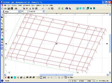
The automated grounding system design uses the following technologies and procedures.
First, an appropriate preliminary grid design is selected and retrieved from a database of predefined
grids, based on the input data provided, such as the size and the geometrical proportions of the grid, the
soil structure, the fault current injected, and the safety criteria. These predefined grids have been
previously analyzed and stored in databases which contain grid performance information in uniform and
layered soil models. The database can be dynamically updated based on the currently analyzed
grounding systems.
Second, this initial design is refined automatically and dynamically by varying the number of horizontal
and vertical conductors in the grid in an attempt to improve its performance and meet the safety
constraints, while reducing the overall cost of the grid. Note that the real soil model (not the equivalent
layered soil used in the database search) is used in this process. The analysis and safety evaluation are
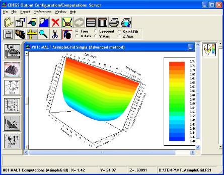
carried out by a grounding analysis module. The ground potential rise (GPR), touch and step voltages
are computed and compared to the maximum values given by the IEEE or IEC standards, or by
user-supplied thresholds. Horizontal or vertical conductors are added or removed depending on the
GPR, touch and step voltage deviations from the desirable safe values. The method used to conduct the
design refinement steps employs approximate functions to determine the number of conductors that can
be added or removed from the design at each step of the iteration. These functions have been derived
based on observations and analysis of the extensive results stored in the database.
The process provides a manual option that allows the user to provide an initial grid design defined by
the number of conductors along the grid sides, and the characteristics of the conductors and rods. The
program then refines this grid automatically.
Go back...
