
| |
| |
| |
| |
| |
| |
packages that can automatically design an entire grounding site
located in multilayered soil. The packages are accurate, efficient,
reliable and most of all, validated extensively with verifiable resullts
published in the most reputable scientific journals.
Yet, despite their unique and poweful capabilities, these packages are affordable and
can be customized to meet your most challenging problems as well as your tighest
budgets.
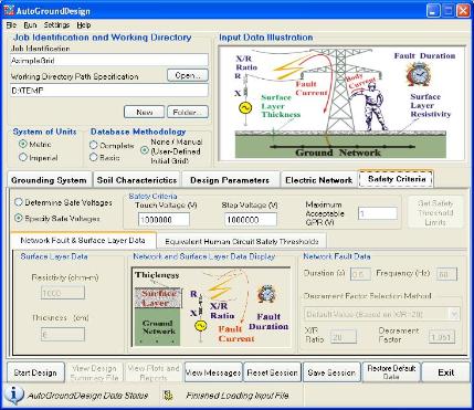
AutoGroundDesign
The AutoGroundDesign engineering tool
offers powerful and intelligent functions
that help electrical engineers design safe
grounding installations quickly and
efficiently. A two-step approach is used
for the automated grounding system
design. The grid database is, optionally,
the starting point of any automated
design and will cover most grids that are
encountered in practice. Next, the initial
design is refined recursively using
rule-based techniques and algorithms to
improve its performance and meet safety
constraints, while reducing the overall
cost of the grid. Extensive collections of
predefined grids have been analyzed,
constructed and can be easily updated
by the user. A strategy has been devised
to quickly find an appropriate grid, while
at the same time minimizing the size of
the database. The time devoted to
design a safe and cost-effective
grounding grid is minimized by the use of
such automation techniques and
appropriate databases.
Introduction
The design of grounding systems is often based on rough guidelines, derived from engineering experience. It is
frequently a trial-and-error procedure and can be quite time-consuming, since it is too difficult to account for the
large number of variables (geometrical proportions of the grid, its depth, the nature of the soil and of the grid’s
conductors, whether or not grounding rods are attached to the grid, etc…) that can affect the grid’s
performance. The ultimate objective of AutoGroundDesign is to use a database and rule-based automated
grounding system design method to meet design requirements (such as ground potential rise, touch voltage,
step voltage, and ground resistance limits), given the soil structure, dimensions of the grid area, characteristics
of conductors, configuration of the grid, and fault current discharged by the grid.
Features
The 2004 release version of AutoGroundDesign has the following unique features:
| Generates grounding system designs based on a simple description of the substation site. The data | ||
| entry requirements are reduced to a minimum: environment settings, soil data, grounding grid zone, fault current in the grid, safety related data, and automated design parameters and controls. | ||
| Models grounding systems and evaluates their performance; it is suited to analyze and design a | ||
| grounding grid as long as the longitudinal impedances of the ground conductors can be neglected. | ||
| Analyzes and designs rectangular grounding grids consisting of horizontal and vertical arrangements of | ||
| bare conductors buried in uniform and multilayered soils. | ||
| Carries out automated design with several procedures, such as Automatic, Midpoint, Linear, and User- | ||
| Defined methods. These procedures will specify the performance and progress of the automated design process appropriately and use ground grid databases, smart search algorithms and techniques, and user-supplied criteria and constraints more efficiently. | ||
| Allow users to specify if ground rods are to be used in the design of the final grid and ground rod | ||
| characteristics. If yes, the rods are distributed over the whole grid area. | ||
| Computes earth potentials at specific soil locations called observation points that are determined | ||
| automatically by the program. | ||
| Has three other modes of operations besides the Automatic Grounding System design mode in order to | ||
| simplify various grounding / earthing tasks. In any one of these three modes, a wide selection of grounding systems can be analyzed assuming uniform or layered soils. Typical systems include array of rods, array of horizontal wires, circular or rectangular plates, hemispherical electrodes, radial wires, etc. The other modes of operations are: |
- Ground Resistance Estimator. In this mode the resistance of any systemcan be determined accurately very
quickly. - Electrode Configuration Predictor. The appropriate configuration of a grounding system having a given size (i.e.,
number of conductors along each side, etc.) that meets a specific resistance is determined easily using this mode
of operation. - Electrode Dimension Predictor. The appropriate size of a grounding system having a specic shape and that
meets a specific resistance can be determined easily using this mode of operation.
For more information information on AutoGroundDesign and its development history proceed to this page.
Automated Grounding System Design Structure
The automated grounding system design software integrates the following modules and has a structure shown
below.
This core and controlling module has a simple interface that allows a user to establish an automated grounding
system design quickly and efficiently. The ultimate objective of this module is to manage and coordinate input
data, safety criteria and progress decisions in order to obtain a grid design that meets all requirements. The
overall automated design parameters are controlled by this module to select the methodology used to obtain
the initial design of the grounding systems, specify which grid database methodology is to be used for the
automated design, and specify the maximum number of design iterations as well as the rate at which the
design of the grid evolves.
Grounding Analysis Module
This module is used to analyze power system ground networks subjected to AC or DC power frequency
currents discharged into various soil structures. It computes the safety performance of the grounding grid, in
terms of GPR, touch and step voltages. Since it is assumed that the grid is an equipotential structure, the
locations of the current injection points within the ground network do not play a significant role, i.e. the
longitudinal impedances of the ground conductors can be neglected.
Soil Analysis Module
This module is dedicated to the development of equivalent earth structure models based on measured soil
resistivity data. It can generate models with many horizontal layers, as well as vertically and exponentially
layered soil models.
Fault Current Distribution Analysis Module
This module calculates the fault current distribution in multiple terminals, transmission lines and distribution
feeders using minimum information and a simple set of data concerning the network. It provides the actual fault
current flowing into a grounding grid, as well as currents in the shield wires, tower structures and cable
sheaths. Self and mutual impedances of the shield wires and cable sheaths are also computed and available.
Safety Module
This module generates safety threshold values based on IEEE Standard 80, IEC Standard 479, user’s own
standard or a hybrid combination of these standards. The computed safety voltage limits are used to decide
whether to stop or continue the design process. The parameters to determine the safety voltage limits are:
fault clearing time, earth surface covering layer (e.g., crushed rock) resistivity, earth surface covering layer
thickness, equivalent subsurface layer resistivity (this is the resistivity of the soil beneath the earth surface
covering layer), body resistance, optionally specified foot resistance and resistance of protective wear, such as
gloves or boots, and fibrillation current threshold computation method.
View, Plot and Report Tools
A CAD-based module is used to view or edit three-dimensional grounding grids consisting of straight-line
segments. The line segments represent either metallic conductors or observation profiles. They can be viewed
from any direction, in a variety of ways. Another report and graphics module serves as a powerful output
processor to display the computation results in various graphical or print formats. This module also has the
capability to view the input data and even launch the grounding analysis module.
Read More...
Note:
The Soil Analysis Module and Fault Current Distribution modules are presently stand-alone modules. They will be integrated into the
AutoGroundDesign package in the next update.